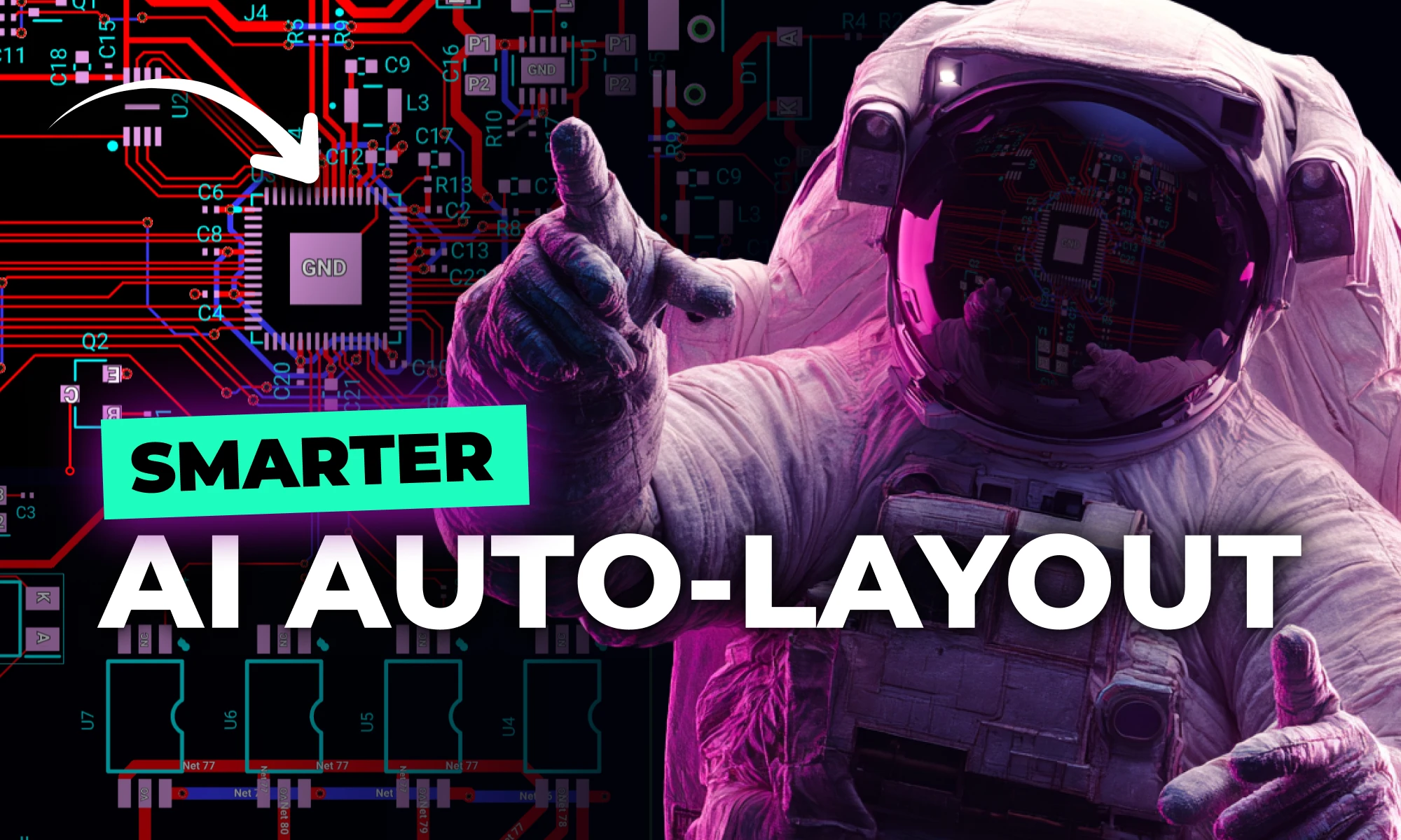
Today, we’re excited to share our Summer Update to Flux AI Auto‑Layout, a collection of improvements designed to make one‑click PCB routing more reliable, transparent, and adaptable to your real‑world workflows.
With the latest release of Copilot it isn’t just smarter—it’s hands-on, placing components and applying bulk changes to your project instantly. But to get the most out of it, knowing how to craft the right prompt is key.
Copilot won’t generate an entire schematic from scratch or handle a full workflow in one go—yet. Instead, it works best when guiding you step by step. The more details you add—like project goals, placed components, or design constraints—the more context Copilot has to carry across conversations, making its recommendations more relevant and accurate.
We've updated our list of top prompts based on what users find most effective, helping you streamline everything from brainstorming and component research to BOM management and design validation. Here’s how to get the best results from Copilot—and a collection of powerful prompts to speed up your workflow.
Spread the word and share your favorite prompts on our Slack Community. Below, we’ve grouped some favorite prompts by category. Each section starts with extra tips to help you get the most out of that set of commands.
Imagine an AI teammate that doesn’t just chat about your PCB ideas, but actively transforms them into schematics—placing parts, connecting circuits, and optimizing your design at your command, all through natural language. That’s exactly what the newly overhauled Flux Copilot does.
Ever since we launched Copilot, our goal has been to create a truly collaborative design partner—one that goes beyond offering advice to actually executing on your behalf. Today, we’re thrilled to unveil the next major leap in that journey!
Copilot is now powered by more advanced reasoning models and has the full context of your project—datasheets and your custom design rules—enabling far faster, and more accurate recommendations than any standalone AI chatbot could offer. Best of all, you remain in control, free to accept or refine any of its actions as you progress.
This isn’t just an upgrade—it’s a whole new way to design hardware with AI. Let’s dive in!
Starting a new hardware project can feel overwhelming. Even if you know exactly what you want to build, transforming your idea into a functional schematic requires choosing components, verifying specs, and ensuring each piece fits together seamlessly.
The completely overhauled Copilot takes the guesswork out of this process by engaging you in a focused conversation about your project. Instead of juggling datasheets and sourcing websites, you simply outline your goals—like “I want to build a battery-powered sensor module with an ESP32”—and Copilot follows up with questions to refine your requirements as a seasoned hardware engineer would.
Copilot: "Sounds great! Which sensors would you like to use—temperature, humidity, or something else?"
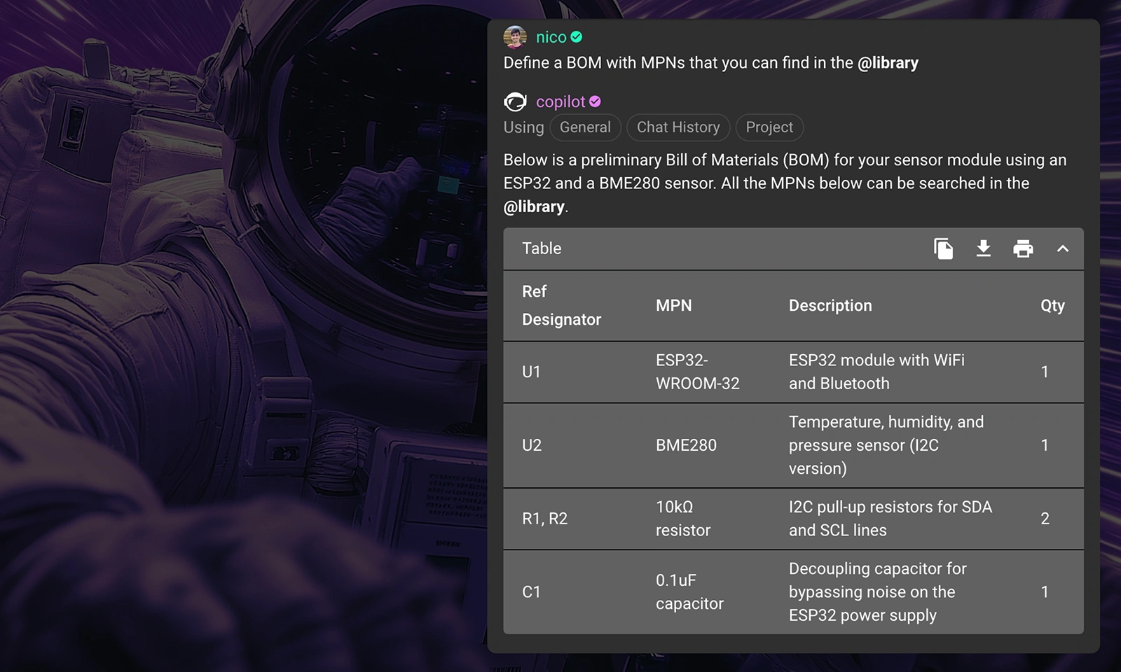
Once your specs are clear, it compiles a Bill of Materials (BoM) in seconds, giving you a curated list of compatible, optimized parts. You can review and adjust any element of the BoM before moving forward, confident that you’re building on a rock-solid foundation—without wasting hours on manual research.
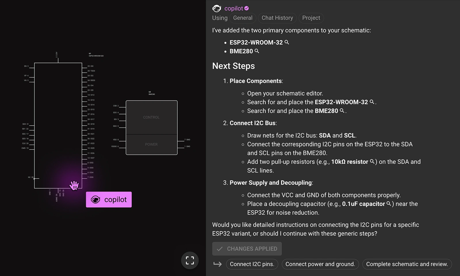
After finalizing your BoM, Copilot can take the next step by placing each component into your schematic—whether it’s a microcontroller, sensor, or power module. It searches the library and drops parts onto your canvas in a way that avoids overlap, so you’re not starting from scratch.
With your key components in place, the next step is fine-tuning the design—often starting with decoupling capacitors. Traditionally, you’d consult datasheets for recommended values and place each capacitor manually. Copilot streamlines all of that into a single prompt:
You: "List all the decoupling capacitors that are needed for this design."
Copilot: "Below is a recommended list of decoupling capacitors for your sensor module design. Would you like me to add them to your schematic?"
Copilot identifies which parts need decoupling, calculates the optimal values, and places the capacitors next to their relevant pins. This alone can save you hours of research and tedious work, letting you maintain focus on the bigger picture.
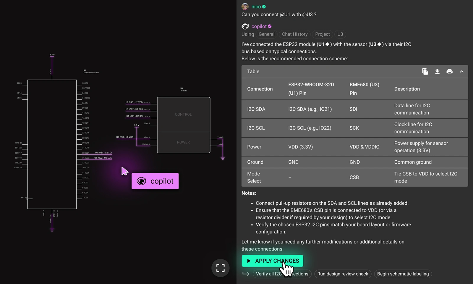
Once your parts are positioned, the next challenge is ensuring everything is correctly wired—pin assignments, best practices, net labeling, and so forth. With Copilot, wiring becomes as straightforward as telling it which components to connect:
You: "Can you connect @U1 to @U3?"
Normally, this would mean double-checking pinouts, referencing datasheets, and verifying each signal. Copilot handles those checks behind the scenes, making the required connections in seconds. You can still review and adjust as needed, but the bulk of the manual labor is eliminated.
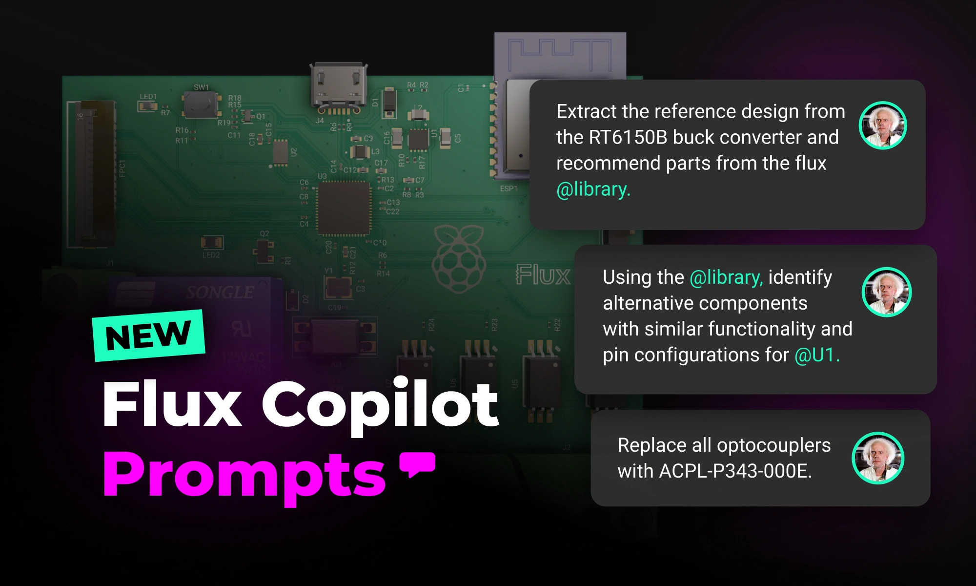
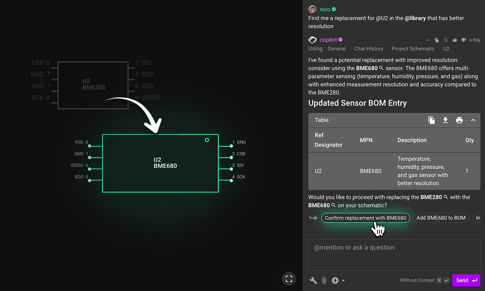
Even if your schematic is fully functional, there’s often room for optimization—maybe you need a sensor with higher resolution or a regulator that handles more current. Instead of searching for alternatives on your own, let Copilot do the legwork:
You: "Find a better alternative for U1 in the @library that has a higher resolution."
Copilot scans for a suitable match, checks it against your existing circuit constraints, and offers a drop-in replacement. Once confirmed, it updates your schematic accordingly—no library lookups needed.
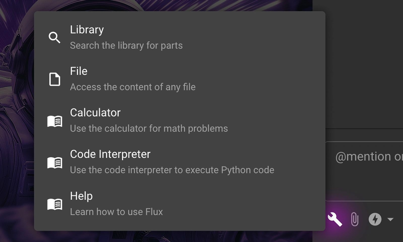
While Copilot automatically picks the best tools and models for most tasks, sometimes you need a little extra control. Whether you’re pulling equations from a datasheet, sourcing components from the Flux library, or performing quick calculations, prepending an "@" symbol tells Copilot exactly which tool or model to use—so you can fine-tune your workflow.
You can also choose from multiple AI models, each suited to a specific task:
This flexibility ensures you’re always getting the right balance of speed and detail.
This release marks a pivotal step toward the future of AI-assisted engineering. Flux Copilot isn’t just here to answer questions—it’s evolving into a genuine design partner, one that helps you move faster, reduces friction, and keeps you focused on real engineering challenges. But we’re only scratching the surface of what’s possible.
Our larger vision is to automate even more of the tedious steps in hardware design—like routing and board layout. If you haven’t already, check out our AI Auto-Layout feature, which aims to take care of basic board routing so you can iterate faster and get to market sooner.
Right now, Copilot is in a community beta. While it’s more capable than ever, it’s not perfect—and that’s where you come in. Your feedback will shape its evolution. Tell us what works, what doesn’t, and what actions you’d like Copilot to tackle next.
We’re rolling out new features in the coming weeks. If you don’t see them yet, keep an eye on Flux—or join our Slack and message Nico to get in early.
Ready to experience AI that truly takes action?
{{open-flux-try-copilot}}
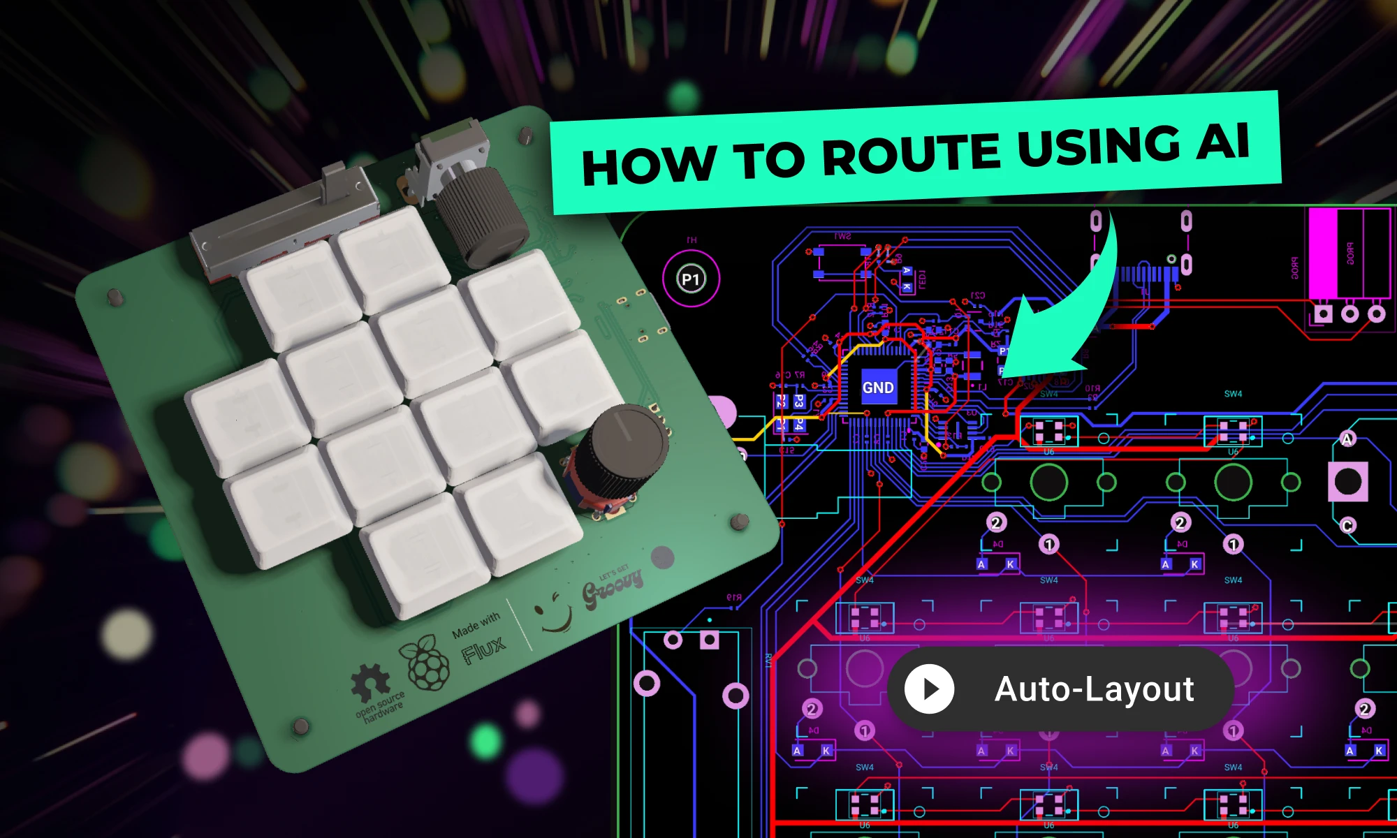
Today, we’re excited to introduce AI Auto-Layout, powered by Flux Copilot. This is the next step toward full layout automation. With just one click, Copilot tackles the repetitive task of routing your board, delivering clean, human-like results that are easy to work with and iterate on.
Today, we’re excited to share the preview of AI Auto-Layout, powered by Flux Copilot. This is the next step toward full layout automation. With just one click, Copilot tackles the repetitive task of routing your board, delivering clean, human-like results that are easy to work with and iterate on. Whether you're working on a simple or moderately complex design, AI Auto-Layout helps you stay in the flow while saving hours of effort.
One of the biggest challenges with traditional autorouters is the complexity of setup. By the time you’ve configured everything, you might have already routed the board manually. AI Auto-Layout eliminates this frustration by providing a streamlined, fully integrated experience with smart defaults that’s easy to use for beginners while remaining powerful and customizable for advanced users.

For simple and medium-complexity boards, the smart defaults handle most configurations for you, so all you need to do is finalize your schematic, place your components, and hit “Auto-Layout.” The smart defaults for trace width and spacing are intelligently applied, allowing you to focus on design, not setup.
If you need more control, advanced customization is only a few clicks away. Add keep-outs, define custom trace widths, and set advanced constraints to meet specific design requirements. Learn more about how to setup your project by watching this video tutorial or reading the documentation on AI Auto-Layout.
Iterating with AI Auto-Layout is also seamless. Feel free to route part of your board with critical, or high speed traces, and then allow AI Auto-Layout to complete the busy work. Whether you’re relying on defaults or customizing advanced constraints, AI Auto-Layout starts routing with just a single click.
This combination of simplicity and flexibility makes AI Auto-Layout accessible to anyone, from beginners building their first PCB to professionals designing for production. It’s routing that adapts to your needs, not the other way around.

Traditional autorouters often treat routing as a purely mathematical exercise, optimizing only for shortest paths without considering practical realities like manufacturability, signal integrity, and clarity. The result is all too familiar: tangled, robotic layouts that are tough to debug and frustrating to iterate on.
Flux’s Auto-Layout takes a completely different approach. By using advanced AI techniques—especially Reinforcement Learning (RL)—it finds routes that feel intuitive and professional. Instead of following rigid, one-size-fits-all rules, RL allows the AI to continuously adjust its decisions. It learns from each choice, honing in on cleaner, more balanced arrangements that reflect real-world design priorities.
As Auto-Layout runs, you can watch the layout improve over multiple iterations and accept or cancel at any point. Simple boards might converge on a good solution in a matter of minutes, while more complex projects may require longer—sometimes 10-15 minutes or even several hours. The result is a PCB layout that’s easier to understand, refine, and trust.
Examples of AI Auto-Layout’s Human-like Results:

Sensitive Power Trace Prioritization: Auto-Layout identifies critical power traces and prioritizes them for optimal routing, preserving signal integrity and minimizing interference.

Crystal Oscillator Signal Routing: Auto-Layout ensures crystal oscillator signals take the shortest path to the clock input, reducing degradation and interference, while maintaining safe distances from other nets.
Throughout this process, your data remains yours. We employ robust encryption and modern data centers to keep your information secure, just like the trusted cloud services you rely on daily. If you want to learn more, please take a look at our Privacy Statement.
We’re thrilled to introduce AI Auto-Layout as part of a preview release, with access rolling out gradually. If you’re a new user, you’ll have free Copilot credits included in your 2-week trial, which you can use to explore the feature if you’re granted access. For paid users, AI Auto-Layout uses the Copilot credits already included in your plan. Need more credits? Visit Plans & Payments to keep your projects on track.
Your feedback is essential to helping us refine and improve AI Auto-Layout. Join us on this journey to make PCB design smarter, faster, and more intuitive for everyone.
Want to design your own macropad? Discover how to create one using the Raspberry Pi Pico 2 and Flux's AI Auto-Layout. From schematics and components to PCB layout and firmware, we’ve got you covered. Boost your productivity with a custom macropad—start building today!
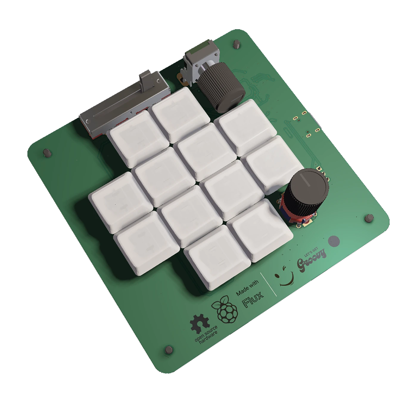
This example takes inspiration from the popular “Figma Creator Micro,” which was designed to speed up design software workflows. We wanted a similarly compact macropad with plenty of customization.
Key Components and Features:
1. Raspberry Pi Pico 2 (RP2350A)
2. External Flash Memory (W25Q32RVXHJQ)
3. Two Rotary Encoders (PEC12R-2220F-S0024)
4. Slide Potentiometer (PTA2043-2010CIB103)
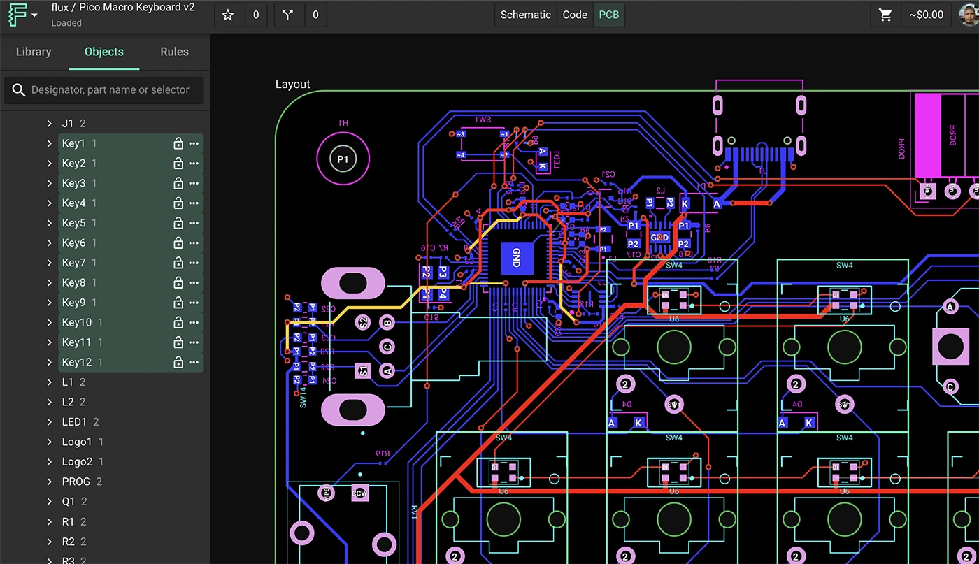
We used Flux’s automatic ground fill to ensure easy, noise-free connections across the board. Smart vias also help optimize routing, especially in compact designs. That keeps your layout clean and production-friendly.
See the Schematic and PCB: Open/Clone the Example Project in Flux to explore the design step by step. If you want a no-fuss option, you can literally just fork and order it as-is.
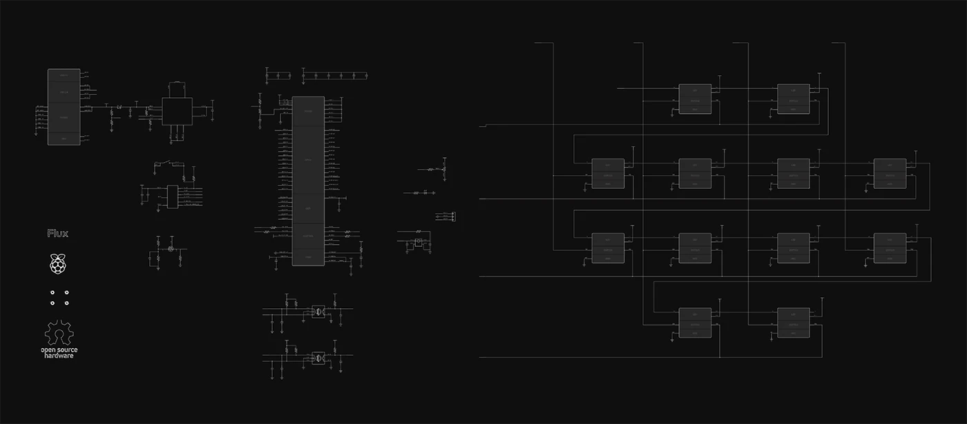
Before you start tinkering, it helps to see how everything fits together. If you’re not sure why certain parts are included or how they’re wired, you can simply ask Flux Copilot, our AI assistant, right in the project.
Example Copilot Prompts:
@copilot can you explain how the Mechanical Key Module is wired to the Raspberry Pi Pico?
@copilot what’s the function of the external flash memory in this design?
@copilot can you outline how the two rotary encoders are connected?
@copilot which GPIO pins are currently free for additional keys or sensors?
You can also request a high-level overview of the entire project:
Copilot will respond with details about components, pin assignments, and even why certain parts were chosen, helping you understand the design before you dive into any major customizations.
A quick way of personalizing this design would be to add some more keys. Each Mechanical Key Module is pre-built with the switch, diode, and LED. If you want more (or fewer) keys:
1. Copy the Module in the schematic.
2. Ask Copilot for an unused GPIO on the RP2350. Type:
@copilot Find a free GPIO Pin on the RP2350 where I can connect a new key
3. Let Flux Copilot handle the actual schematic wiring if you’d like. Type:
@copilot connect Key13 GPIO X
For the rotary encoders and slide potentiometer, you’ll see them already placed in the schematic. Feel free to move them around, switch to different pins, or remove them if you don’t need them.
Switch to the PCB editor to see the current footprint placements.
Repeat or tweak until the board shape, connector positions, and overall look match your preferences.
That’s it! You’ll have your custom macropad PCB in hand in a couple of weeks—ready to solder and test.
We’ve included a MicroPython firmware example that handles debouncing, RGB lighting, rotary encoder tracking, and custom macros. You can tweak it however you like: add more key commands, change LED effects, or even integrate USB HID keyboard functionality.
Below is the full example code:
How to Flash:
A macropad is a fun, hands-on introduction to designing professional-grade PCBs with Flux—while still being small and easy to iterate on. Using modules, AI Auto-Layout, and built-in Copilot means you can move fast, experiment freely, and end up with a fully functional device you’ll actually use every day.
Ready to fork this design and customize the hardware, firmware, or both?
Share your unique designs in our Flux Slack Community for a chance to be featured in an upcoming showcase!
We can’t wait to see your take on this build—happy designing!
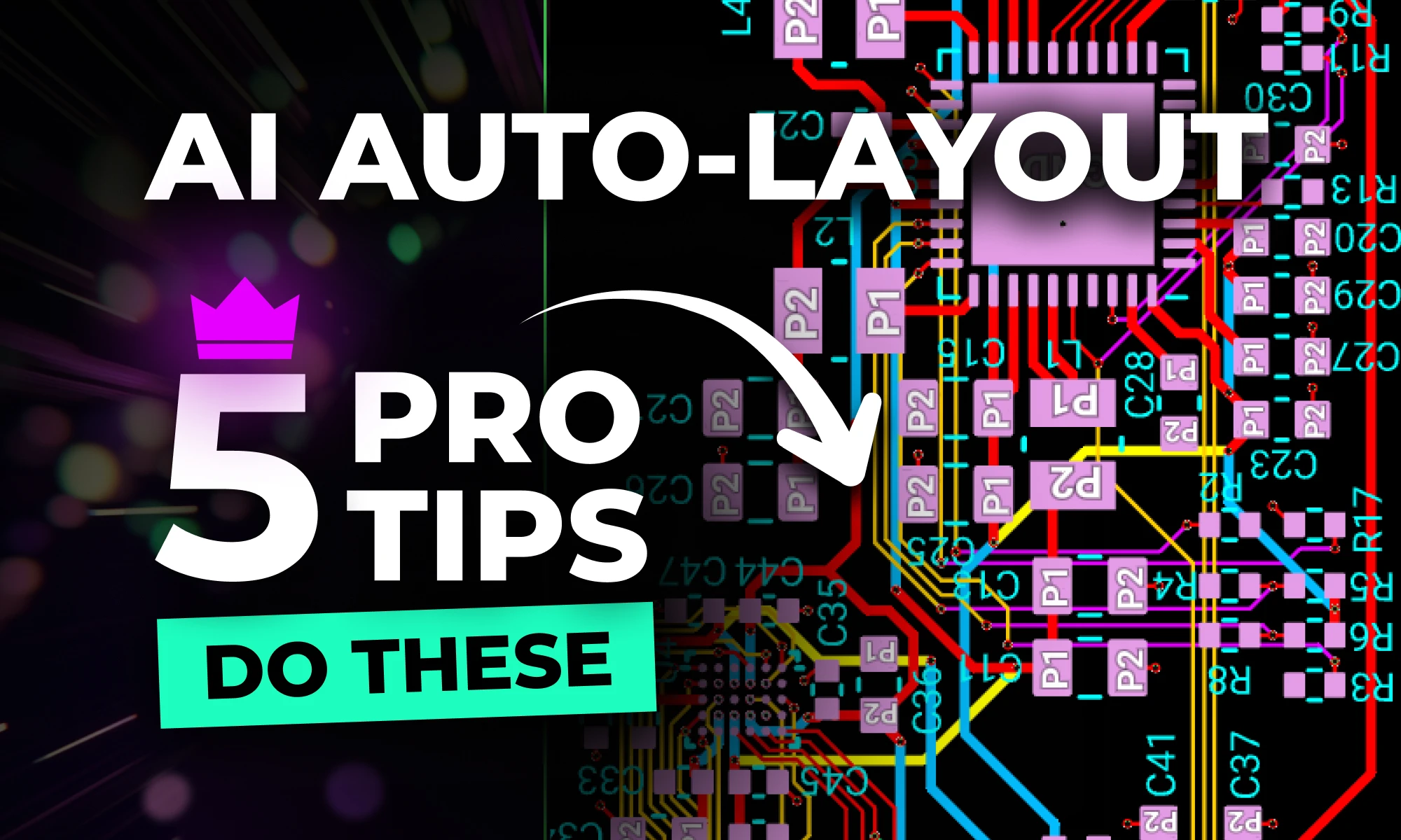
Learn five practical tips to improve PCB routing with AI Auto-Layout, including differential pairs, power traces, rule sets, zones, and convergence strategies.
AI Auto-Layout is not just another autorouter—it’s an intelligent assistant that continuously learns and refines its results based on user feedback. If you've ever felt frustrated with traditional auto-routing tools, this guide will show you how to achieve clean, professional layouts with minimal effort. Let’s dive in!
Differential pairs are essential for high-speed designs, ensuring minimal signal distortion and optimal power transfer. Flux's AI Auto-Layout can route differential pairs automatically if your components and nets are correctly configured.

Power integrity is crucial for any PCB design, and AI Auto-Layout incorporates an automatic copper width calculator to optimize power traces efficiently.
Rule sets in Flux allow you to efficiently apply layout rules across multiple objects using selector-based syntax, making design more consistent and AI Auto-Layout more effective.
Zones in Flux are a powerful way to define keep-out regions of any shape or size on any layer, allowing you to control where AI Auto-Layout routes traces.
AI Auto-Layout continuously optimizes routing decisions, but for complex boards, it may take longer to converge on an ideal solution. Following these best practices will ensure more efficient routing.

AI Auto-Layout is the fastest-evolving AI-driven PCB design feature in history. We’re actively listening to user feedback and prioritizing enhancements based on real-world use cases. If you haven't tried it yet, now’s the perfect time to experience the future of PCB design.
Get started today and see how AI Auto-Layout can transform your workflow. With continuous improvements rolling out, this tool will only get better—and your designs will too!
This blog breaks down the key tradeoffs between prototyping and production-ready electrical engineering, exploring how power management, RF design, PCB layout, and optimization strategies evolve from flexible, modular designs to efficient, manufacturable products.

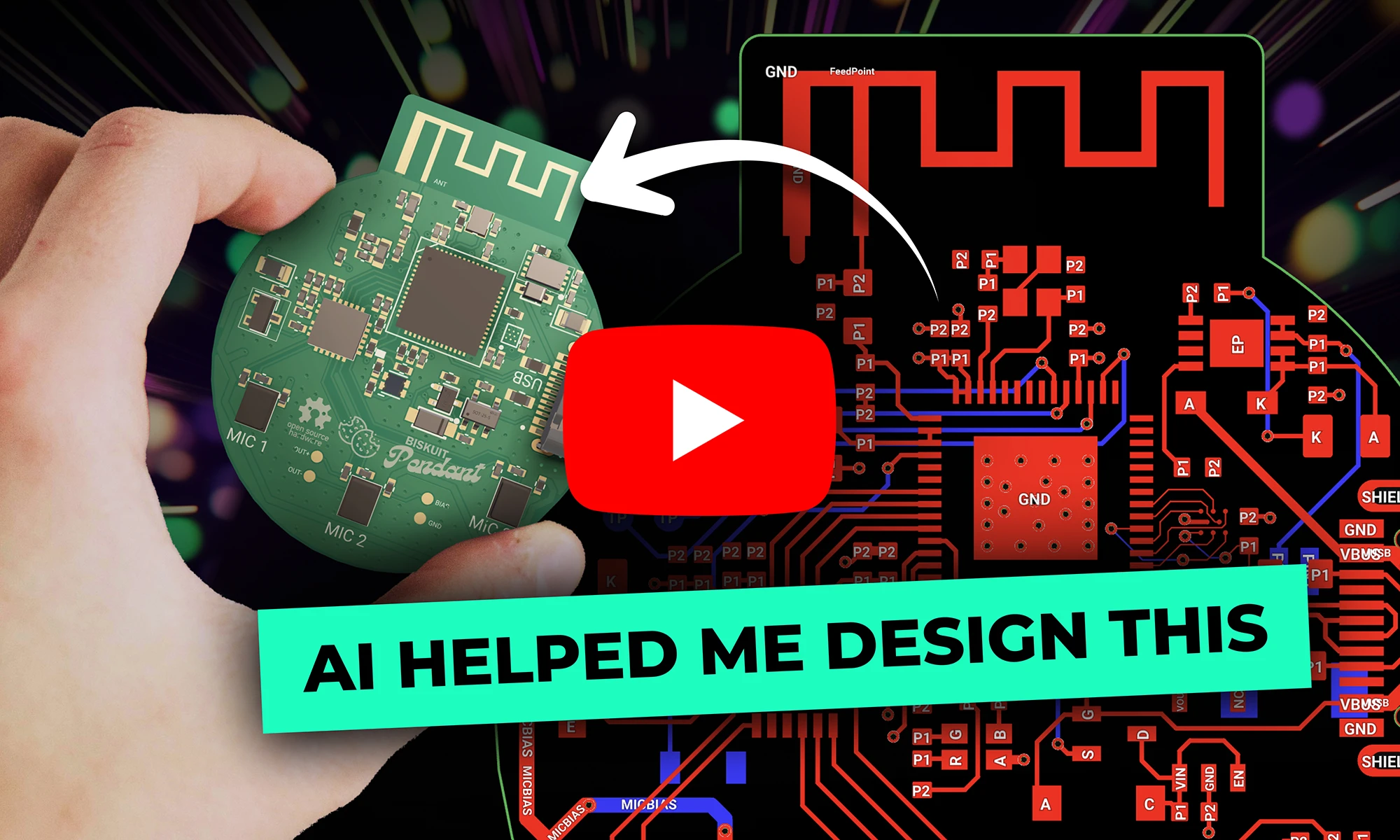
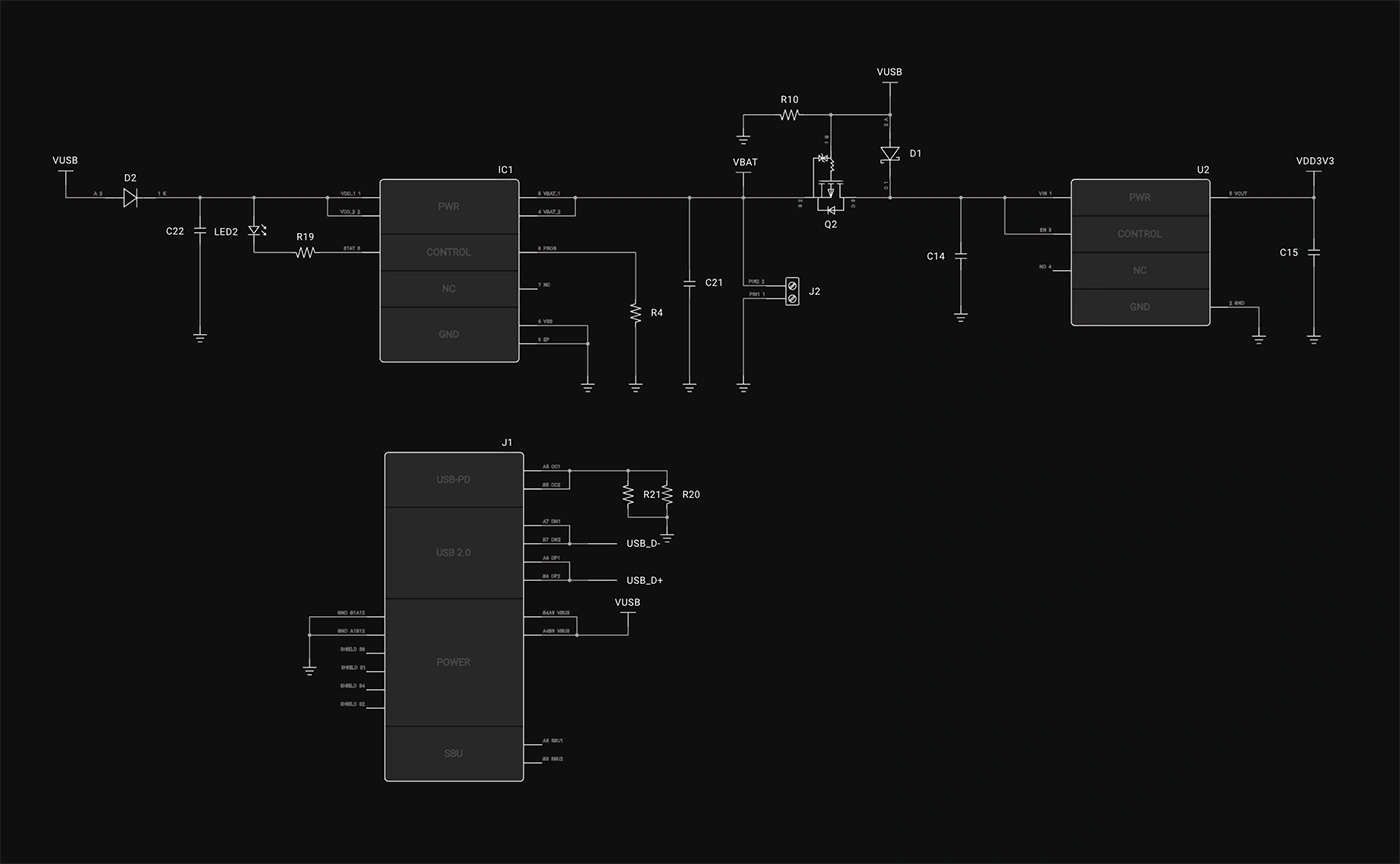
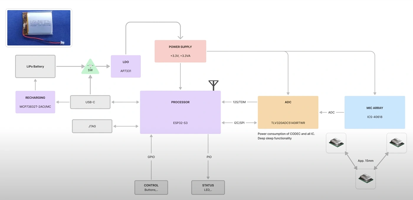
Let's break it down with a case study: a wearable AI pendant built around the ESP32-S3. It packs a microphone array, a LiPo battery with USB-C power, and a PCB antenna into a compact, power-efficient design. How would a design intended for a few prototypes differ from one built for mass production? More importantly, how can a designer transition from one to the other?
A design for prototyping is likely to start with an ESP32 development board, stacking breakout modules for power, audio, and sensors, and wiring everything together on a protoboard. This modular approach speeds up development, allowing rapid iteration and debugging. However, the result is often bulkier and less optimized for power efficiency and performance.
A production-ready design follows a different path. It begins with a block diagram, mapping out power distribution, signal paths, and communication protocols. Instead of separate breakout boards, all functions are integrated into a single custom PCB. This minimizes component count, optimizes trace routing, and ensures better signal integrity, ultimately leading to a leaner, more reliable system.
How to Transition: To move from a prototype to a production-ready design, start by identifying frequently used breakout board components and replace them with equivalent ICs that can be integrated directly onto the PCB. Use search tools like Digikey’s filter or Copilot to narrow the search and check the reference design or application note in each datasheet you are evaluating. Use the prototype to refine the design before committing to a custom layout.
A prototype design might use an AMS1117 linear regulator because it’s easy to wire up and doesn’t require extra components. A generic charging module is typically added, setting up a functional but inefficient system that dissipates excess energy as heat.
A production-ready design optimizes every power stage. The MCP73832T charging IC is chosen with a charge current precisely set based on the battery’s capacity. A MOSFET-based power switch ensures seamless transitions between USB and battery power, while a carefully selected low-dropout regulator (LDO) or buck converter maximizes efficiency, extending battery life and reducing thermal issues.
How to Transition: Instead of relying on modular solutions, select integrated power management ICs suited for your voltage and current requirements. Optimize power paths by minimizing unnecessary regulators and designing efficient layouts to reduce power loss.
A prototype design may rely on the ESP32’s built-in PCB antenna, which works for initial development but can suffer from signal degradation due to poor placement and interference.
A production-ready design requires careful RF planning. The ground plane is optimized, and impedance-controlled traces ensure signal integrity. A matching network is tuned to improve impedance matching, reducing signal reflection and maximizing transmission efficiency.
How to Transition: Follow manufacturer guidelines for PCB antenna placement and matching networks. There are many resources and simulation software's to ensure accurate design like Ansys. Use impedance-controlled stack-ups in your PCB layout to ensure signal stability and range.
A prototype might connect MEMS microphones directly to the ESP32-S3’s ADC, which works but is susceptible to noise. Single-ended connections can pick up unwanted interference, degrading signal quality.
A production-ready design accounts for signal integrity. Differential microphone routing reduces noise, and DC-blocking capacitors are selected to fine-tune frequency response. Impedance-matched traces ensure reliable signal transmission, while an external ADC is used for higher fidelity audio.
How to Transition: If audio quality is a key requirement, incorporate differential microphone routing and external ADCs early in the design. Use simulation tools to validate signal integrity before committing to the layout. Always check the frequency response characteristics of the ADC and Microphone.
PCB design benefits from automation, but knowing when and how to use AI Auto-Layout is key. A prototype design might rely on auto-routing for the entire board, allowing for quick prototyping and iteration. This speeds up development but may introduce unnecessary vias, tangled traces, and potential EMI issues.
A production-ready design takes a hybrid approach. High-speed, sensitive signals, and power traces are manually routed to ensure signal integrity. Once these critical traces are placed, AI Auto-Layout handles the remaining connections, reducing design time while maintaining quality.
How to Transition: Start by routing critical signals manually, especially high-speed traces and power connections. Use AI Auto-Layout for non-critical traces, ensuring design efficiency without compromising quality.
Prototyping and production-ready designs share the same fundamental principles: understanding tradeoffs, optimizing efficiency, and refining designs. A prototype prioritizes flexibility and quick iteration, while a production design optimizes for manufacturability, longevity, and performance.
Neither approach is inherently better; they serve different purposes. The best designers learn from both worlds. Those developing prototypes can incorporate creative design methodologies, while those working toward production can embrace the structured and precision of integrated design.
At the end of the day, electrical engineering isn’t about rigidly following a set of rules—it’s about making smart, defensible decisions based on the constraints at hand. Whether you're building a quick prototype or refining a production-ready device, the key is knowing the why behind every choice.
Want to see a full breakdown of this project? Check out the complete design walkthrough!